What-a-Shame is the name of a musical instrument I designed long ago, and this article tells you what you need to know to build it. The article is not a step-by-step how-to; rather it outlines the underlying ideas and provides the necessary information while leaving things open enough that people can explore the ideas and do things in their own ways. The project isn’t difficult, but it does call for basic handywork with common tools and minimal soldering.
You can see What-a-Shame in action here and read a bit more about it here. In concept, it is a system for mounting a narrow, flexible steel rod so that it’s fixed rigidly at one end and free to vibrate at the other, but held in such a way that the vibrating length of the free end can easily be varied from very short (a couple of inches) to very long (up to about 32″). If you pluck or bow the rod to set it in motion, and then vary the length, then the audible pitch glides up or down. But that’s the least of it: quite a lot of interesting acoustic effects and sonic possibilities come into play with the various tricks you can try.
To bring out the vibrations within the rod, a magnetic pickup is positioned near the mounting point.
Multiplying the possibilities further, a second rod of variable length can be mounted perpendicular to the first, where it can produce its own sounds as well as contacting and interacting with the first rod.
Normally the rods are positioned just above the pickup but not touching, allowing the pickup to respond to their vibrations. But in addition, if you position one of the rods a certain way and start it swinging up and down, then it hammers against the pickup casing with each swing, and this too brings in an important additional vocabulary of sounds.
The flexible rods are typically 36″ long and a little over 1/16″ in diameter (.072″ is typical). The essential components of the rest of the instrument – the variable mounting system and the pickup — can be quite small, at just a few inches across. But for the instrument to vibrate well, the mounting system needs to be solidly immobile. You could achieve this by fixing it to some sort of massive base, but a simpler approach is to clamp it to the edge of a table.
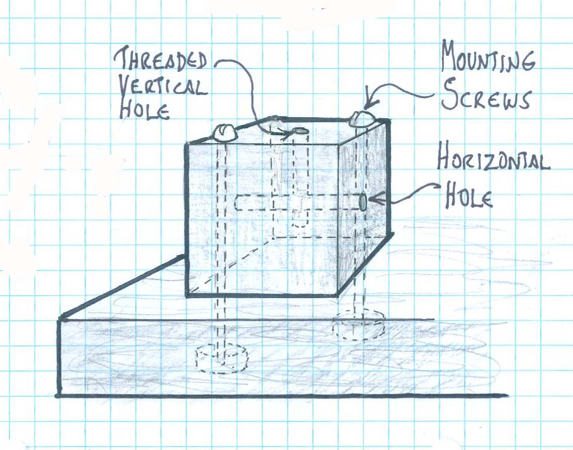
The essential feature is the mounting/sliding system, and the way it works is wonderfully simple. The central element is a small block of wood — a cube of about 1½” or 1¾” of the hardest, strongest wood you can get your hands on. (A block of aluminum, or even steel, would be great, but for working with common tools in a home workshop, a very hard wood is more manageable and will serve adequately.) A hole is drilled horizontally through this cube slightly larger than the diameter or the rod – typically about 1/8″. With the block solidly mounted, you can run the rod through the hole, holding it at one end while the other end extends out from the opposite side of the block. If you flex your end upward, you get a situation in which the rod is forced up against the top of the hole on your end, and down against the bottom of the hole at the other end. (Or vice versa: flex your end or the rod downward, and the rod presses up against the top of the hole opposite.) These two pressure points are enough to give the portion of the rod extending out on the opposite side a rigid base from which it can sustain a vibration well. While holding it this way you can slide the rod back and forth in the hole to vary the free length on the opposite side, and the vibration will sustain as you slide, with the frequency rising or falling as you go.
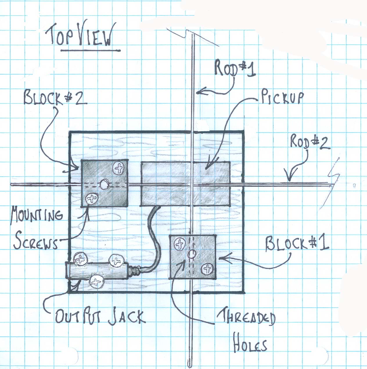
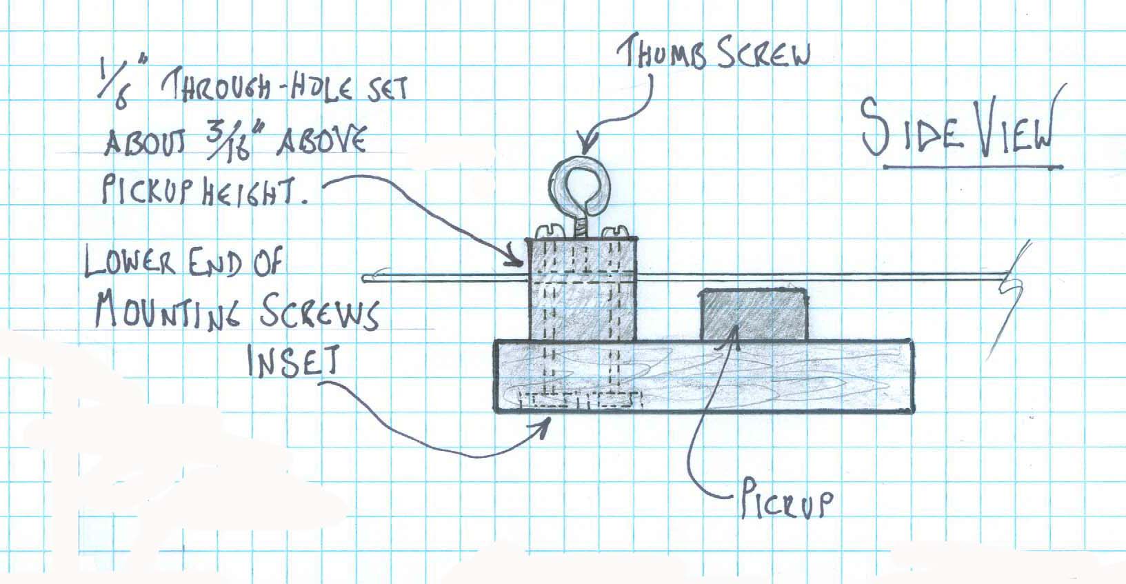
The completed instrument has two such blocks to accommodate the two rods. The two blocks are positioned on a small mounting board in such a way that with both rods in place they’ll cross at right angles to one another. The player has the option of working just one rod alone or two rods in interaction. As shown in the drawing, the pickup is located in front of the two blocks, just below where the rods cross. The positioning of the horizontal holes that the rods pass through is crucial: they should be just high enough that the rods press down against the pickup when angled downward, or clear the pickup by about ¼” when angled upward. The optimal height of this hole thus depends on the height of your pickup as mounted on the mounting board. Or, better: you can have two or three such holes in each block, positioned closely alongside one another at slightly different heights, to offer a choice of rod positionings. There will also be a vertical hole coming down from the top of the block to intersect one of the horizontal rod holes. This hole is threaded so that a thumb screw can, if desired, be twisted down to where it presses against the rod passing through the horizontal hole, temporarily securing it in a particular position.
One could choose to include volume and tone controls for the pickup. In this article we’re keeping things simple and not addressing that. I can recommend some additional electronics, though, in the form of a graphic equalizer and a compressor. Both of these are available as guitarist’s “stomp boxes” and can easily be placed on the tabletop alongside the instrument. If you don’t mind the added expense, they allow some valuable tweaking of the sound and, conveniently, one or the other may provide a local volume control.
Here’s a materials list for the instrument:
The rods: two straight spring steel rods, also known as piano wire, 36″long, .078″ in diameter. Available from many sources, including here.
The pickup: A dual-coil electric guitar pickup that has a very strong casing. (Being dual coil ensures that it will be a suitable shape; not too skinny.) This one is excellent for the purpose because it’s extremely sturdy, suitable in its dimensions, produces a strong signal with low noise, and is very affordable.
Additional electronic hardware: if you don’t intend to include volume and tone controls, the only additional electronic hardware required is an audio jack to solder the pickup output to so you can plug in. Given the likely configuration of the instrument, an inline jack such as this one will probably be most convenient and workable. If the wires coming from the pickup are quite short, you may also need a little extra shielded wire.
The blocks: two cubes, each between 1½” and 1¾”, of the heaviest, hardest wood you can get your hands on. I’ve used ipe, aka ironwood, but other dense hardwoods will do. The height of the block ( 1½” or 1¾”) will depend on the height of your pickup, as you’ll see when you turn the information below into a design on paper.
The base: any wood, about ¾” x 5 ½” x 6″. (The 5 ½” suggested width is chosen for easy availability – it’s a common size for nominal 6” lumber.)
Two thumbscrews allowing the option of tightening the rods in position: I suggest two eye bolts (1⅝” length, 10-24 thread, ⅞” thread length, ⅜” eye diameter) (eyebolts | McMaster-Carr).
Miscellaneous additional hardware: depending on the details of your design, you’ll need some screws and possibly glue for affixing the blocks, the pickup and the jack. Size needed for the these mounting screws will vary depending on the size of your mounting blocks and thickness of the mounting board; typical would be 8-32 x 2¼”.
Optional additional sound activators: threaded rods, about 10″ long can be used for scraping effects. Thread size 10-24 works nicely; slightly bigger or smaller can also work.
The clamps: two clamps of suitable size for clamping the instrument to the edge of a heavy table.
Procedure:
Draw up your design. The graphics shown here represent a typical design; yours may vary to accommodate available materials, the height of your pickup, and so forth.
Cut the two blocks and the base piece.
Drill the 1/8″ horizontal through-holes in the blocks in the specified locations.
Drill the top-down holes to intersect with the through-holes. If you go with the suggested 10-24 thread eyebolts for the hold-downs, make these pilot holes 9/64″ (or numeric bit size 27 = .144”; these smaller-than-usual sizes reflect that fact that wood is softer than metal.) Don’t just drill to where the vertical hole intersects the horizontal; drill well beyond that to leave room for the tap you’ll be threading with later. Thread the holes using a 10-24 tap. Threading in wood is not nearly as difficult as threading in metal. It’s important that the threaded portion of the hole be fairly long – like a half inch or so – to make up for the fact that wood will strip more easily than metal if over-stressed by screwing the thumb screw down too tight.
Attach the blocks to the base in their correct locations. It’s important that they be really well attached – glue alone won’t be enough. I suggest gluing and screwing, and for the screwing I suggest not wood screws, but machine screws running through to an inset nut in the bottom of the base. In locating the holes for the mounting screws, be sure to avoid placing the screw holes where they will intersect with the horizonal through-holes.
Solder the jack to the end of the pickup’s output wires.
Mount the pickup on the mounting board in the location shown in the drawing. The mounting should be good and solid, directly on the board. How you do this depends on the pickup. If the pickup has mounting screw holes, they may or may not be useful depending on how they’re positioned … you may even need to break off the tabs that hold the mounting screw holes if they prevent a placing the bottom of the pickup flat on the board. If the pickup is provided with mounting springs, don’t use them. It may be that the most workable way to mount the pickup is simply to use a strong glue that bonds the two materials (pickup casing and wood) such as Goop or E6000. Glue the underside of the pickup directly to the board, perhaps with some strategically placed wood screws around the sides to prevent lateral movement.
Mount the output jack to the board at a suitable location. If you’re using a cylindrical inline jack as suggested above, an easy way to hold it securely is with three countersink screws, two on one side near the ends and one at the center of the opposite side, screwed down so that the angled undersides of the screw heads work together in pressing the jack casing down against the mounting board and against each other.
That completes the assembly of the instrument. To set it up for playing, use the two clamps to clamp it to the corner of a sturdy table top angled so that the active part of the rods, when extending out, are free to vibrate and swing without hitting anything. Also, position it so that at least one of the rod extensions on the hand-held side also extends beyond the table edge to allow freedom of movement for the player. As mentioned earlier, you may find it valuable to run the output signal through a compressor, as this is helps to control for the fact that some of the sounds this instrument makes are significantly louder than others. You might also like running it through a graphic equalizer as a way of balancing the tone in a way that pleases your ear. These gadgets can be placed on the table nearby.
As for playing technique — anything goes. Things to experiment with:
One rod alone or two in interaction.
Long and short active lengths in the rods, plus all the glissandos between.
Different sorts of plucks — for instance, with long lengths, lots of fingernail close to the block can be good for long and short lengths alike, while various sorts of press-and-release or pull-and release are good for large amplitudes at long rod lengths.
Rods positioned to vibrate freely above the pickup or rods positioned at a downward angle to hammer against the pickup.
Fun with the threaded rods scraping over the rods at different locations.
Fixing one rod in place at a chosen length with a thumb screw while manipulating the length of the other rod.
Combinations of all of these.
What-a-Shame’s pickup allows you to hear a lot of subtle oscillations happening in the rod. With so many ways to manipulate the sound, there really is quite a lot going on in there. Many of the most interesting effects stem from the fact that the frequency range of the fundamental mode of vibration in the rod is huge. At the low end it starts somewhere around 1Hz or 2Hz when the vibrating portion of the rod is extended to something close to its full length – that’s one or two cycle per second, far below the lower limit of the human hearing range. At the upper end, when the vibrating portion is just an inch or two long, the fundamental reaches somewhere up toward 2000Hz (with overtones higher still). The very low fundamental frequencies of the extended rod, being subsonic, are inaudible as pitches, but if you’ve positioned the rod so that it hammers against the pickup, then you hear the individual hits as a recurring pulse or rhythm. But even without hammering, the pickup lets you hear other oscillations within the rod even when the fundamental is subsonic, in the form of overtones. These are the many higher modes of vibration which sound along with the fundamental. Interesting things happen if you start with the rod fully extended so that the fundamental is subsonic, and then continue to sound it (by plucking near the base or whatever) as you shorten it. When it’s long, you don’t hear the fundamental, nor, typically, do you hear much of the second or third modes; instead you mostly hear whichever of the higher modes happen to fall comfortably within the hearing range. With progressive shortening, all the modes rise. One by one, those previously subsonic modes gradually become discernable as they come into the hearing range. Each mode will seem to dominate the perceived tone for a time as it passes through the heart of the range. Then, as it continues its ascent toward the upper reaches it too starts to fade into the background, even as the following lower modes one by one rise to take their turns in the limelight. If you really focus on the sound, you can hear each mode in turn having its moment in the sun as it passes through the heart of the range, before some other usurper from below appears and increasingly dominates the tone.
Another interesting effect: When you placed two rods at right angles in interaction, they create exotic rhythm patterns in the ways they hammer against each other and/or on the pickup. Often these arise from their differing periods going in and out phase with one another, creating emergent polyrhythms.
When you anchor one of the rods with the thumbscrew at a fairly long active length and then set it swinging in a wide arc, hammering on the pickup with each swing, it can keep going for quite a while. In this it can function as a semi-self-playing instrument: after setting it in motion you can let it continue on its own, providing a pulsing underpinning or accompaniment for other sounds or instruments you may layer over it.
The threaded rods are to be used as separate hand-held implements. They can be scraped over the main sounding rods at various locations to make a variety of fascinatingly bestial sounds.
I could point out many more interesting effects, but I’ll stop here. You’ll discover more as you take time to explore the instrument.